Cellular Sensor
GoSafer Security procedures and references for Cellular Sensor.
- Cellular Sensor
- Alarm.com Flex IO® sensor
- Alarm.com Flex IO® sensor - Data Sheet
- Alarm.com Flex IO® sensor - Installation Guide
- Alarm.com Flex IO® sensor - LED Patterns and Troubleshooting
- Alarm.com Flex IO® sensor - Supported Use Cases
- Can an Alarm.com Flex IO® sensor be installed in a mobile home, trailer, or RV?
- Can an Alarm.com Flex IO® sensor report alarms to a monitoring station when opened?
- What are the battery power options and requirements for an Alarm.com Flex IO® sensor?
- What is a battery tamper and mounting tamper?
- What is the Cat-M cellular network?
Cellular Sensor
GoSafer Security Knowledge Base
This operational reference is organized for GoSafer Security customers and staff. Alarm.com product names are retained where required for technical accuracy.
Overview
This GoSafer Security section brings together resources for Cellular Sensor, including setup, configuration, everyday use, and troubleshooting. Choose the related page that matches your device, feature, or task, and follow the current manufacturer guidance linked on that page.
| Platform | General / Device |
|---|---|
| Content type | Troubleshooting |
| Source last updated | 2026-03-06 |
Procedure
Source and support
For GoSafer Security assistance, visit gosafersecurity.com.
Original Alarm.com reference: https://answers.alarm.com/Customer/Website_and_App/Cellular_Sensor
Always verify safety, installation, compatibility, and current UI details against the original manufacturer documentation before operational use.
Alarm.com Flex IO® sensor
GoSafer Security Knowledge Base
This operational reference is organized for GoSafer Security customers and staff. Alarm.com product names are retained where required for technical accuracy.
Overview
This is primarily a video or reference page. Open the original article link below for the current content.
| Platform | General / Device |
|---|---|
| Content type | Troubleshooting |
| Source last updated | 2026-03-26 |
Procedure
Data sheets
Alarm.com Flex IO® sensor - Data Sheet
Installation guides
Alarm.com Flex IO® sensor - Installation GuideAlarm.com Flex IO® sensor - Supported Use Cases
How-to troubleshooting guides
Alarm.com Flex IO® sensor - LED Patterns and Troubleshooting
Frequently asked questions
Can an Alarm.com Flex IO® sensor be installed in a mobile home, trailer, or RV?The Alarm.com Flex IO® sensor can be used in mobile or moving applications, but reliable operation depends on adequate cellular signal strength in all locations where the sensor travels.Can an Alarm.com Flex IO® sensor report alarms to a monitoring station when opened?No. The Alarm.com Flex IO® sensor is designed for property awareness only and cannot forward signals to a monitoring station.What are the battery power options and requirements for an Alarm.com Flex IO® sensor?What is a battery tamper and mounting tamper?What is the Cat-M cellular network?
Source and support
For GoSafer Security assistance, visit gosafersecurity.com.
Original Alarm.com reference: https://answers.alarm.com/Customer/Website_and_App/Cellular_Sensor/Alarm.com_Flex_IO_sensor
Always verify safety, installation, compatibility, and current UI details against the original manufacturer documentation before operational use.
Alarm.com Flex IO® sensor - Data Sheet
GoSafer Security Knowledge Base
This operational reference is organized for GoSafer Security customers and staff. Alarm.com product names are retained where required for technical accuracy.
Overview
This is primarily a video or reference page. Open the original article link below for the current content.
| Platform | General / Device |
|---|---|
| Content type | How-to / Configuration |
| Source last updated | 2025-09-30 |
Procedure
Step-by-step guide: Screenshots and videos are placed with the instruction they illustrate.
Overview
The Alarm.com Flex IO® sensor enables new levels of flexibility for monitoring valuable property and assets anywhere that LTE connectivity is available. Whether used with a backyard gate or a remote storage unit, the Alarm.com Flex IO® sensor empowers users to keep an eye on what matters most. It can be used with the included magnet to monitor doors, gates, and other entryways. It also comes equipped with input and output options for integrating compatible devices that lack long-range connectivity.
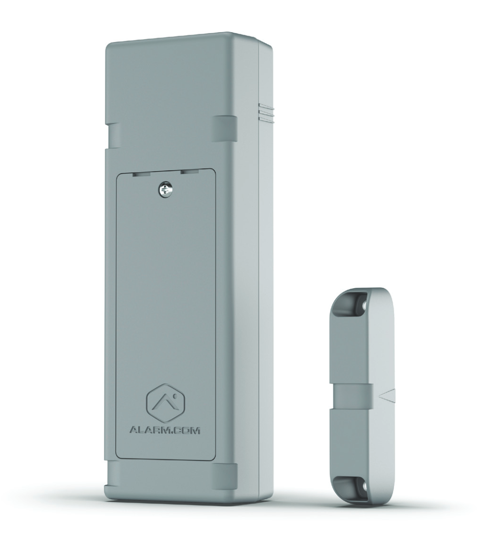
Features
- Detect open/close using magnetic reed switch
- Detect state change for third-party device using Loop Input
- Change state of third-party and device using Relay Output (requires DC power to support always-on cellular connection)
For more information about supported use cases, see Alarm.com Flex IO® sensor - Supported Use Cases.
In the box
- Optional EOL (end of line) resistor to detect cut wires. EOL resistor can be 300 kΩ or higher. Normally Open configuration is preferred for low power usage.
- Optional mount tamper and battery door tamper alerts
- Multiple mounting options, including screws or zip ties.
- Multiple carrier options:
- Verizon (US only)
- AT&T (US and Canada)
Specifications
|
Ingress Protection
|
IP56 |
|---|---|
|
Temperature |
Battery life will be optimal between temperatures of 32°F to 131°F (0°C to 55°C), though the device can operate from -40°F to 131°F (-40°C to 55°C). |
|
Reed Switches |
3 unique reed switch locations to choose from that can be activated with included magnet. |
|
Loop Input |
|
|
Relay Output
|
Caution: Can never be connected directly to control electrical loads. This will damage the device. |
|
Dimensions
|
|
|
Power
|
|
|
Battery Power |
|
|
Maximum Installation Height |
2000 meters above ground level |
Source and support
For GoSafer Security assistance, visit gosafersecurity.com.
Original Alarm.com reference: https://answers.alarm.com/Customer/Website_and_App/Cellular_Sensor/Alarm.com_Flex_IO_sensor/Alarm.com_Flex_IO_sensor_-_Data_Sheet
Always verify safety, installation, compatibility, and current UI details against the original manufacturer documentation before operational use.
Alarm.com Flex IO® sensor - Installation Guide
GoSafer Security Knowledge Base
This operational reference is organized for GoSafer Security customers and staff. Alarm.com product names are retained where required for technical accuracy.
Overview
This is primarily a video or reference page. Open the original article link below for the current content.
| Platform | Customer Website |
|---|---|
| Content type | Troubleshooting |
| Source last updated | 2025-06-04 |
Procedure
Step-by-step guide: Screenshots and videos are placed with the instruction they illustrate.
Overview
The Alarm.com Flex IO® sensor enables new levels of flexibility for monitoring valuable property and assets anywhere that LTE connectivity is available. Whether used with a backyard gate or a remote storage unit, the Alarm.com Flex IO® sensor empowers users to keep an eye on what matters most. It can be used with the included magnet to monitor doors, gates, and other entryways.
Important: The Alarm.com Flex IO® sensor is an awareness device that is not intended for life safety use cases.
The following are some example applications:
- Shed Doors
- Storage Units
- Chicken Coop
- Fences
- Delivery Boxes
- RV Doors
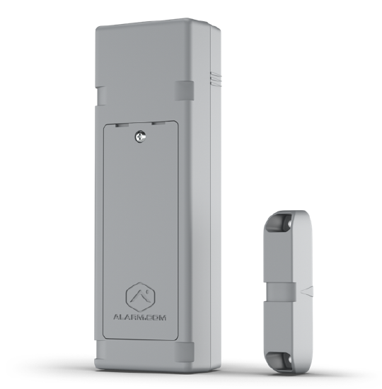
Equipment
In the box:
- Alarm.com Flex IO® sensor
- Magnet
- 4x AA 1.5V lithium batteries
- 4x #8 Phillips screws
- 3x zip ties
Additional required tools and supplies:
- Phillips head screwdriver
- Paper clip (to press the sensor's diagnostic button; see Cellular signal strength)

Installation wizard
Start the installation wizard
Using the Alarm.com app:
- Log in to the Alarm.com app.
- Tap Menu.
- Tap Add Device.
- Tap Flex Sensor.
- Follow the on-screen instructions to set up the device. The install wizard will take you through the steps outlined in the following expandable sections.
Using the GoSafer Security customer portal (powered by Alarm.com):
- Log in to the GoSafer Security customer portal (powered by Alarm.com).
- Tap Settings.
- Tap Manage Devices.
- Tap Add Device.
- Tap Flex Sensor.
- Follow the on-screen instructions to set up the device. The install wizard will take you through the steps outlined in the following expandable sections.
Enter the device serial numberIcn Chevron Up
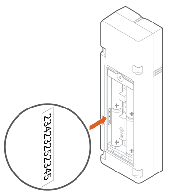
The device serial number is printed inside the battery compartment as shown in the following image.
Insert the batteriesIcn Chevron Up
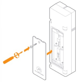
- Remove the front card.
- Install the included batteries.
- Close the battery compartment door, and tighten the screw securely.
- Make sure the battery door screw is securely tightened to clear the battery door tamper. This will also ensure a waterproof seal.
- If this screw is not fully tightened, the LED will show a single red blink every 2 seconds.
Caution: Be careful to not over-torque the screw. Power tools should be avoided.
Note: Throughout the installation process the LED will start blinking at multiple intervals. This is normal.
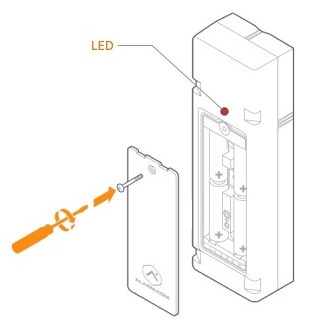
Battery compatibility
- Lithium batteries are required for this device. Under normal conditions, battery life is expected to be 2 years.
- Any 1.5 V lithium battery should work. Alkaline batteries or any battery greater than 1.5 V (e.g., the Saft 3.6 V) should not be used.
Note: If batteries are not installed, a Low Battery trouble condition appears on the account.
Name your sensorIcn Chevron Up
Give your Alarm.com Flex IO® sensor device a name to help you identify it (e.g., Shed or Fence).
Check for device signalIcn Chevron Up
To check for device signal:
- Bring the sensor to the location you would like to install it.
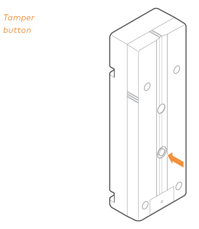
- Press the tamper button to check the signal. This tamper button must be fully pressed (until you hear a clicking sound).
- The install wizard will look for the device signal.
- A Success message should appear if successful.
- If unable to get a signal from your device, try again. If you continue to experience issues, contact flexsupport@alarm.com for additional support.
Select magnet positionIcn Chevron Up
Like a standard door/window contact, the Alarm.com Flex IO® sensor can be installed with the accompanying magnet to detect activity at potential entryways.
To determine your installation orientation, consider the following:
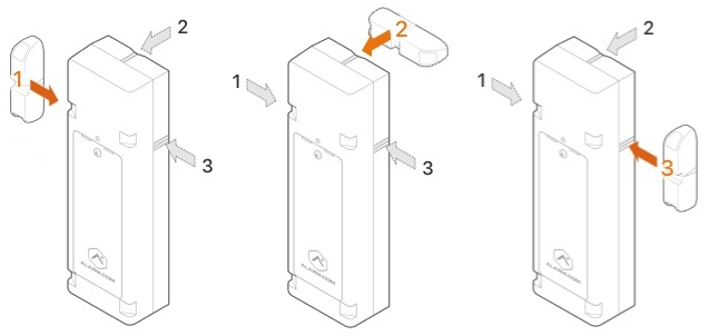
- Three separate magnet positions are available. Only one magnet position can be active at a time.
- Use the tick marks on the sides of the device for guidance:
- | = Position 1
- || = Position 2
- ||| = Position 3
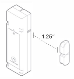
- The magnet should be positioned no more than 1.25 inches from the device.
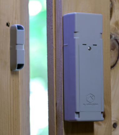
In the following example photo, Position 1 would be selected since the magnet is to the left of the sensor.
If Position 2 or 3 were selected, the sensor would not accurately report when the door opens/closes.
Mounting options and installationIcn Chevron Up
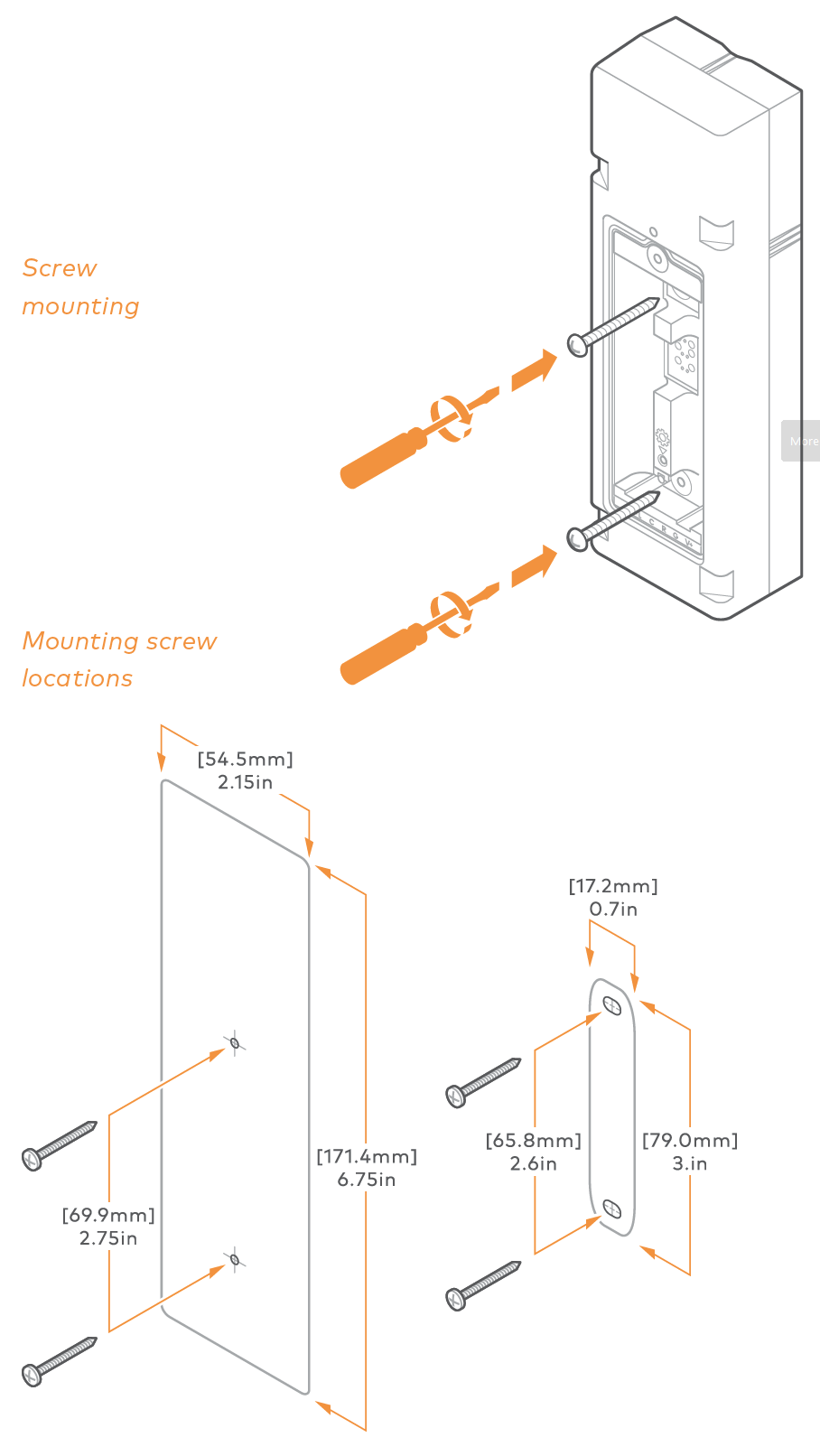
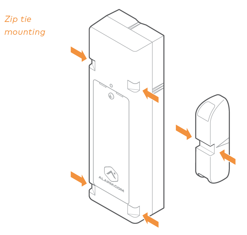
The Alarm.com Flex IO® sensor can be mounted using either screws or zip ties.
Important: A mounting tamper is located on the back of the Alarm.com Flex IO® sensor. This tamper button must be fully pressed (until you hear a clicking sound) to avoid reporting a mounting tamper malfunction.
If using screws:
- Remove batteries to avoid damage to the batteries. Screw mounting holes are located in the battery compartment.
- Use two #8 Phillips screws to puncture the gasket and securely mount the Alarm.com Flex IO® sensor.
- Take care not to over-torque the screws. Power tools should be avoided. If pilot holes are necessary, a drill bit size of 5/64’’ is recommended.
- Once mounted, insert the batteries and close the battery door.
If using zip ties:
- The batteries and battery cover can remain installed.
- Use the zip tie grooves at the top and bottom of the Alarm.com Flex IO® sensor to ensure a secure installation so that the Alarm.com Flex IO® sensor is mounted flush to the surface. The magnet also has a zip tie groove across the center.
- Zip ties should have a maximum width of 0.34 inches. UV resistant zip ties are recommended.
- To establish the connection with your Flex, open the battery door and close it tightly.
Sensor test Icn Chevron Up
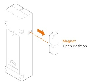
- Verify that your magnet is in closed position.
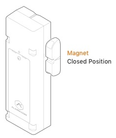
- Open the magnet to trigger the sensor. The LED should blink yellow twice when the device is tripped. This prompts the Alarm.com Flex IO® sensor to communicate.
- The install wizard will verify if your device is working properly. If there are no errors, the sensor installation is now successfully complete.
If you receive a Mounting Tamper Error:
- Ensure the mounting tamper is fully pressed against a surface, and then click Try Again.
- You will hear a clicking sound when the tamper button is fully pressed. A mounting tamper is also indicated by an alternating single Red and Yellow LED pattern.
- If this is not possible, you can also disable the mounting tamper error by disabling the Mounting Tamper Error Enabled toggle switch.
If you receive a Battery Door Error:
- Verify the battery door is screwed closed otherwise water damage may occur.
- Ensure the magnet is in closed position, open the magnet to trigger the sensor, and then click Try Again.
If you receive a Communication Error:
- Verify the magnet is less than 1.25 inches away from the Alarm.com Flex IO® sensor.
- Move the magnet and Alarm.com Flex IO® sensor closer to each other, and then click Try Again.
Post-Installation Checklist
- The Alarm.com Flex IO® sensor is installed flush to the mounting surface. If the mounting tamper is enabled, the tamper button on the back of the device should be pressed in.
- The LED is not blinking. The only LED activity should occur when the device is activated, which should result in 2 yellow blinks.
- For more information on LED patterns, see Alarm.com Flex IO® sensor - LED Patterns and Troubleshooting.
- Device activations are being reported in the history on the website and app.
Cellular signal strength
Cellular signal strength can be checked using the following steps.
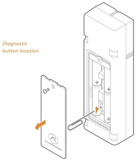
- Using a screwdriver, remove the battery door. Leave the battery cover off. The device LED should now be active.
- Hold the Alarm.com Flex IO® sensor in the installation location.
- Using a paper clip, push the diagnostic button for 5 seconds, then release. The device LED should now be active.
Once diagnostic mode is initiated, the LED will display the cell signal strength in a continuous loop for 2 minutes based on the patterns below. It may take up to 30 seconds for the signal strength to be acquired.
As you move the device, any changes in signal strength will be displayed by updates to the LED pattern. A signal strength of 2 bars or greater is recommended.
|
Signal strength |
LED pattern |
LED visual |
|---|---|---|
|
Signal strength pending |
Solid red |
 |
|
0 bars |
Single red LED blink every 8 seconds |
 |
|
1 bar |
1 red LED blink, followed by 1 yellow LED blink |
 |
|
2 bars |
1 red LED blink, followed by 2 yellow LED blinks |
 |
|
3 bars |
1 red LED blink, followed by 3 yellow LED blinks |
 |
|
4 bars |
1 red LED blink, followed by 4 yellow LED blinks |
 |
|
5 bars |
1 red LED blink, followed by 5 yellow LED blinks |
 |
|
6 bars |
1 red LED blink, followed by 6 yellow LED blinks |
 |
For more information about the Alarm.com Flex IO® sensor LEDs, see Alarm.com Flex IO® sensor- LED Patterns and Troubleshooting.
SpecificationsIcn Chevron Up
|
Ingress Protection
|
IP56 |
|---|---|
|
Temperature |
Battery life will be optimal between temperatures of 32°F to 131°F (0°C to 55°C), though the device can operate from -40°F to 131°F (-40°C to 55°C). |
|
Reed Switches |
3 unique reed switch locations to choose from that can be activated with included magnet. |
|
Loop Input |
|
|
Relay Output
|
Caution: Can never be connected directly to control electrical loads. This will damage the device. |
|
Dimensions
|
|
|
Power
|
|
|
Battery Power |
|
|
Maximum Installation Height |
2000 meters above ground level |
Regulatory InformationIcn Chevron Up
Important: The Alarm.com Flex IO® sensor is a monitoring device that is not intended for life safety use cases.
FCC
This device complies with Part 15 of the FCC Rules. Operation is subject to the following two conditions:
- this device may not cause harmful interference, and
- this device must accept any interference received, including interference that may cause undesired operation.
Changes or modifications not expressly approved by the manufacturer could void the user’s authority to operate the equipment.
Note: This equipment has been tested and found to comply with the limits for a Class B digital device, pursuant to Part 15 of the FCC Rules. These limits are designed to provide reasonable protection against harmful interference in a residential installation. This equipment generates, uses and can radiate radio frequency energy and, if not installed and used in accordance with the instructions, may cause harmful interference to radio communications. However, there is no guarantee that interference will not occur in a particular installation. If this equipment does cause harmful interference to radio or television reception, which can be determined by turning the equipment off and on, the user is encouraged to try to correct the interference by one or more of the following measures:
- Reorient or relocate the receiving antenna.
- Increase the separation between the equipment and receiver.
- Connect the equipment into an outlet on a circuit different from that to which the receiver is connected.
- Consult the dealer or an experienced radio/TV technician for help.
ISED
This device contains licence-exempt transmitters(s)/receiver(s) that comply with Innovation, Science and Economic Development Canada’s licence-exempt RSS(s). Operation is subject to the following two conditions:
- This device may not cause interference.
- This device must accept any interference, including interference that may cause undesired operation of the device.
Cet appareil contient des émetteurs/récepteurs exemptés de licence conformes à la norme Innovation, Sciences, et Développement économique Canada. L'exploitation est autorisée aux deux conditions suivantes:
- L'appareil ne doit pas produire de brouillage.
- L'utilisateur de l'appareil doit accepter tout brouillage radioélectrique subi, même si le brouillage est susceptible d'en compromettre le fonctionnement.
Contact Information
If you are experiencing difficulties with an Alarm.com Flex IO® sensor installation, contact flexsupport@alarm.com and we’ll be happy to assist you further.
Source and support
For GoSafer Security assistance, visit gosafersecurity.com.
Original Alarm.com reference: https://answers.alarm.com/Customer/Website_and_App/Cellular_Sensor/Alarm.com_Flex_IO_sensor/Alarm.com_Flex_IO_sensor_-_Installation_Guide
Always verify safety, installation, compatibility, and current UI details against the original manufacturer documentation before operational use.
Alarm.com Flex IO® sensor - LED Patterns and Troubleshooting
GoSafer Security Knowledge Base
This operational reference is organized for GoSafer Security customers and staff. Alarm.com product names are retained where required for technical accuracy.
Overview
The following table displays what the red and yellow LEDs indicate on the Alarm.com Flex IO® sensor.
| Platform | General / Device |
|---|---|
| Content type | Troubleshooting |
| Source last updated | 2023-11-15 |
Procedure
Step-by-step guide: Screenshots and videos are placed with the instruction they illustrate.
The following table displays what the red and yellow LEDs indicate on the Alarm.com Flex IO® sensor.
|
State/Description |
Red LED behavior |
Yellow LED behavior |
|---|---|---|
|
Device booting up |
None |
1 blink  |
|
Device reboot |
None |
None |
|
Diagnostic mode (Bluetooth troubleshooting activated)
For more information, see the signal strength table on Alarm.com Flex IO® sensor - Installation Guide. |
Signal strength indicator, repeats every 8 seconds Pattern based on signal strength. Rate of 1 blink per second. 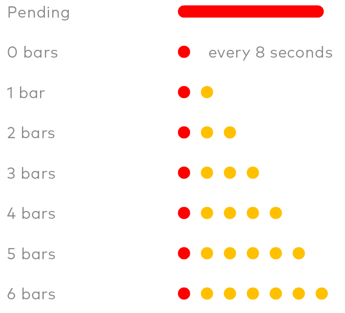 Note: This mode prevents any other pattern from displaying. |
Signal strength indicator, repeats every 8 seconds Pattern based on signal strength. Rate of 1 blink per second. Note: This mode prevents any other pattern from displaying. |
|
Device in idle mode |
None |
None |
|
Device cell modem unable to connect to cell tower To troubleshoot, contact flexsupport@alarm.com. |
2 blink, repeats every 2 seconds  |
None |
|
Device cell modem/SIM not provisioned with carrier To troubleshoot, contact flexsupport@alarm.com. Device will likely need to be returned. |
3 blink, repeats every 2 seconds  |
None |
|
Device unable to connect to Alarm.com To troubleshoot, contact flexsupport@alarm.com. |
4 blink, repeats every 2 seconds  |
None |
|
Contact sensor opens If the device is not reliably reporting open/close events, confirm the magnet position setting matches the installation orientation. |
None |
2 blink  |
|
Contact sensor closes If the device is not reliably reporting open/close status, confirm the magnet position setting matches the installation positions. |
None |
2 blink |
|
Battery door tamper |
1 blink, repeats every 2 seconds  |
None |
|
Device mount tamper |
Alternate Red & Yellow (Red, Yellow, Red, Yellow, 5 second Pause, Repeat)  |
Alternate Red & Yellow (Red, Yellow, Red, Yellow, 5 second Pause, Repeat) |
|
Device low battery |
1 long Red blink (5 seconds) Will occur only following an open/close activation and will follow the normal yellow activity blinks.  |
None |
Source and support
For GoSafer Security assistance, visit gosafersecurity.com.
Original Alarm.com reference: https://answers.alarm.com/Customer/Website_and_App/Cellular_Sensor/Alarm.com_Flex_IO_sensor/Alarm.com_Flex_IO_sensor_-_LED_Patterns_and_Troubleshooting
Always verify safety, installation, compatibility, and current UI details against the original manufacturer documentation before operational use.
Alarm.com Flex IO® sensor - Supported Use Cases
GoSafer Security Knowledge Base
This operational reference is organized for GoSafer Security customers and staff. Alarm.com product names are retained where required for technical accuracy.
Overview
The following table describes some use cases for Alarm.com Flex IO® sensor. Note: The Alarm.com Flex IO® sensor is designed to self-monitor property and assets. The Alarm.com Flex IO® sensor does not report alarms to a monitoring station.
| Platform | General / Device |
|---|---|
| Content type | FAQ / Explanation |
| Source last updated | 2024-05-24 |
Procedure
Step-by-step guide: Screenshots and videos are placed with the instruction they illustrate.
The following table describes some use cases for Alarm.com Flex IO® sensor.
Note: The Alarm.com Flex IO® sensor is designed to self-monitor property and assets. The Alarm.com Flex IO® sensor does not report alarms to a monitoring station.
| How will the Alarm.com Flex IO® sensor be used? | Example Applications |
|---|---|
| Contact Sensor allows you to use the Flex and built-in reed switch to monitor if something is opened or closed. |
|
| Wired Contact Sensor allows you to wire a contact sensor to the Flex using the loop input terminal. | Install the Flex IO in a discrete and convenient location and wire the sensor to your door, window, or entry point |
| Pull-Apart Sensor allows you to use the Flex with a pull-apart or Magnapull sensor. This could be used to determine if something is moved from its location. |
|
| Gate Control allows you to use the Flex with a compatible gate controller. |
Install the Flex IO to allow users to open their gate using Alarm.com. Important: Remote open commands require powered gates in the auto-close configuration. |
| Virtual sensor integrated with an IQ panel | Install the Flex IO to integrate with a Qolsys IQ security panel. |
Source and support
For GoSafer Security assistance, visit gosafersecurity.com.
Original Alarm.com reference: https://answers.alarm.com/Customer/Website_and_App/Cellular_Sensor/Alarm.com_Flex_IO_sensor/Alarm.com_Flex_IO_sensor_-_Supported_Use_Cases
Always verify safety, installation, compatibility, and current UI details against the original manufacturer documentation before operational use.
Can an Alarm.com Flex IO® sensor be installed in a mobile home, trailer, or RV?
GoSafer Security Knowledge Base
This operational reference is organized for GoSafer Security customers and staff. Alarm.com product names are retained where required for technical accuracy.
Overview
The Alarm.com Flex IO® sensor can be used in mobile or moving applications, but reliable operation depends on adequate cellular signal strength in all locations where the sensor travels.
| Platform | General / Device |
|---|---|
| Content type | FAQ / Explanation |
| Source last updated | 2026-03-06 |
Procedure
Yes. However, this would be subject to the signal strength of the device at all locations that the Alarm.com Flex IO® sensor could travel to.
For more information about the cellular network the Alarm.com Flex IO® sensor uses, see What is the CAT-M Cellular Network?.
Source and support
For GoSafer Security assistance, visit gosafersecurity.com.
Original Alarm.com reference: https://answers.alarm.com/Customer/Website_and_App/Cellular_Sensor/Alarm.com_Flex_IO_sensor/Can_an_Alarm.com_Flex_IO_sensor_be_installed_in_a_mobile_home%2C_trailer%2C_or_RV%3F
Always verify safety, installation, compatibility, and current UI details against the original manufacturer documentation before operational use.
Can an Alarm.com Flex IO® sensor report alarms to a monitoring station when opened?
GoSafer Security Knowledge Base
This operational reference is organized for GoSafer Security customers and staff. Alarm.com product names are retained where required for technical accuracy.
Overview
No. The Alarm.com Flex IO® sensor is designed for property awareness only and cannot forward signals to a monitoring station.
| Platform | General / Device |
|---|---|
| Content type | How-to / Configuration |
| Source last updated | 2022-01-21 |
Procedure
No. The Alarm.com Flex IO® sensor is designed for property awareness only and cannot forward signals to a monitoring station.
To self-monitor the Alarm.com Flex IO® sensor, set up sensor activity monitoring notifications for sensor openings. For more information about setting up notifications, see Create a notification for an Alarm.com Flex IO® sensor.
If the customer also has video cameras, an automation rule can be created to trigger a recording when the Alarm.com Flex IO® sensor is opened. For more information about setting up video recording rules, see Create a video clip recording rule for an Alarm.com Flex IO® sensor.
Source and support
For GoSafer Security assistance, visit gosafersecurity.com.
Original Alarm.com reference: https://answers.alarm.com/Customer/Website_and_App/Cellular_Sensor/Alarm.com_Flex_IO_sensor/Can_an_Alarm.com_Flex_IO_sensor_report_alarms_to_a_monitoring_station_when_opened
Always verify safety, installation, compatibility, and current UI details against the original manufacturer documentation before operational use.
What are the battery power options and requirements for an Alarm.com Flex IO® sensor?
GoSafer Security Knowledge Base
This operational reference is organized for GoSafer Security customers and staff. Alarm.com product names are retained where required for technical accuracy.
Overview
The Alarm.com Flex IO® sensor uses four 1.5V AA lithium batteries. These batteries are included in the box. Under normal conditions, battery life is expected to be 2 years. Caution: Alkaline batteries or any battery greater than 1.5 V (e.g., the Saft 3.6 V) should not be used. The Alarm.com Flex IO® sensor device will only be awake when there is activity on the Alarm.com Flex IO® sensor contact sensor. The Alarm.com Flex IO® sensor only communicates sensor status updates one-way to the Alarm.com cloud, and does not receive any commands.
| Platform | General / Device |
|---|---|
| Content type | How-to / Configuration |
| Source last updated | 2023-11-15 |
Procedure
The Alarm.com Flex IO® sensor uses four 1.5V AA lithium batteries. These batteries are included in the box. Under normal conditions, battery life is expected to be 2 years.
Caution: Alkaline batteries or any battery greater than 1.5 V (e.g., the Saft 3.6 V) should not be used.
The Alarm.com Flex IO® sensor device will only be awake when there is activity on the Alarm.com Flex IO® sensor contact sensor. The Alarm.com Flex IO® sensor only communicates sensor status updates one-way to the Alarm.com cloud, and does not receive any commands.
Note: If batteries are not installed, a Low Battery trouble condition appears.
For more information about installation, see Alarm.com Flex IO® sensor - Installation Guide.
Source and support
For GoSafer Security assistance, visit gosafersecurity.com.
Original Alarm.com reference: https://answers.alarm.com/Customer/Website_and_App/Cellular_Sensor/Alarm.com_Flex_IO_sensor/What_are_the_battery_power_options_and_requirements_for_an_Alarm.com_Flex_IO_sensor%3F
Always verify safety, installation, compatibility, and current UI details against the original manufacturer documentation before operational use.
What is a battery tamper and mounting tamper?
GoSafer Security Knowledge Base
This operational reference is organized for GoSafer Security customers and staff. Alarm.com product names are retained where required for technical accuracy.
Overview
The Alarm.com Flex IO® sensor has two tamper switches-a battery tamper and a mounting tamper. The following table outlines how each tamper is triggered, resolved, and what LEDs flash locally to report it. Alarm.com Flex IO® sensor tampers can be enabled/disabled during the Flex DIY Wizard Installation process. For more information, see Alarm.com Flex IO® sensor - Installation Guide.
| Platform | General / Device |
|---|---|
| Content type | How-to / Configuration |
| Source last updated | 2023-11-15 |
Procedure
Step-by-step guide: Screenshots and videos are placed with the instruction they illustrate.
The Alarm.com Flex IO® sensor has two tamper switches-a battery tamper and a mounting tamper.
The following table outlines how each tamper is triggered, resolved, and what LEDs flash locally to report it.
| Tamper type | How it's triggered | How to resolve | LED report |
|---|---|---|---|
| Battery tamper | Triggers anytime the battery door is open | The battery door must be fully screwed down | 1 red blink every 2 seconds |
| Mounting tamper |
Triggers if the device is moved from its mounted location Note: The tamper is located on the back of the device |
The tamper button must be fully pressed (until a clicking sound is heard) |
Alternating red and yellow blinks |
Alarm.com Flex IO® sensor tampers can be enabled/disabled during the Flex DIY Wizard Installation process. For more information, see Alarm.com Flex IO® sensor - Installation Guide.
Source and support
For GoSafer Security assistance, visit gosafersecurity.com.
Original Alarm.com reference: https://answers.alarm.com/Customer/Website_and_App/Cellular_Sensor/Alarm.com_Flex_IO_sensor/What_is_a_battery_tamper_and_mounting_tamper%3F
Always verify safety, installation, compatibility, and current UI details against the original manufacturer documentation before operational use.
What is the Cat-M cellular network?
GoSafer Security Knowledge Base
This operational reference is organized for GoSafer Security customers and staff. Alarm.com product names are retained where required for technical accuracy.
Overview
The Cat-M network is a portion of the LTE cellular network, dedicated to low-power Internet of Things (IoT) devices. Compared to traditional (Cat-1) LTE, it has a smaller bandwidth and slower upload speeds but is capable of handling significantly more devices through its unique way of controlling traffic on the cell towers. One of the primary advantages of Cat-M is that it utilizes flexible power-saving modes to drastically increase the battery life of devices. For example, Cat-M devices like Alarm.com Flex IO® sensors communicate over the cellular network when needed (for example, when the sensor is opened or closed, tampered with, or has a low battery) and conserve power when the device is idle. Note: Alarm.com Flex IO® sensors are currently only available on CAT-M Verizon and CAT-M AT&T.
| Platform | General / Device |
|---|---|
| Content type | FAQ / Explanation |
| Source last updated | 2023-11-15 |
Procedure
The Cat-M network is a portion of the LTE cellular network, dedicated to low-power Internet of Things (IoT) devices. Compared to traditional (Cat-1) LTE, it has a smaller bandwidth and slower upload speeds but is capable of handling significantly more devices through its unique way of controlling traffic on the cell towers.
One of the primary advantages of Cat-M is that it utilizes flexible power-saving modes to drastically increase the battery life of devices. For example, Cat-M devices like Alarm.com Flex IO® sensors communicate over the cellular network when needed (for example, when the sensor is opened or closed, tampered with, or has a low battery) and conserve power when the device is idle.
Note: Alarm.com Flex IO® sensors are currently only available on CAT-M Verizon and CAT-M AT&T.
Source and support
For GoSafer Security assistance, visit gosafersecurity.com.
Original Alarm.com reference: https://answers.alarm.com/Customer/Website_and_App/Cellular_Sensor/Alarm.com_Flex_IO_sensor/What_is_the_Cat-M_cellular_network
Always verify safety, installation, compatibility, and current UI details against the original manufacturer documentation before operational use.